E-mail
WhatsApp



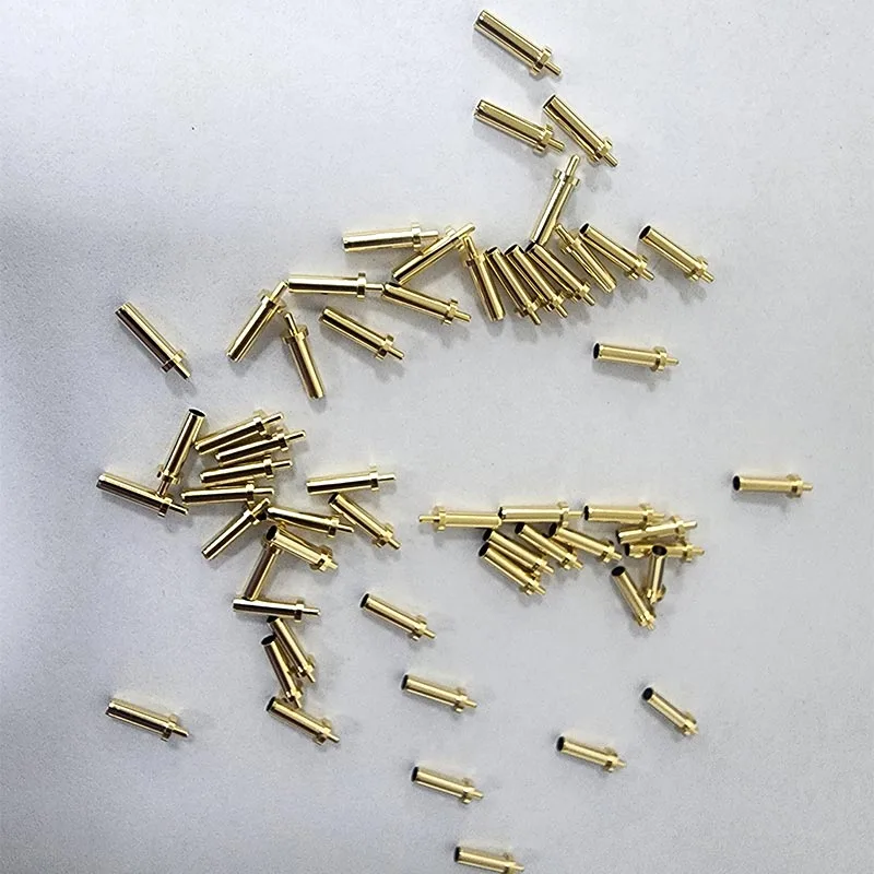
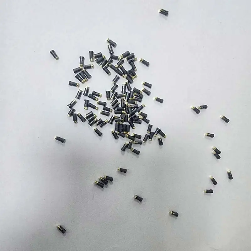
SMT Ground Pin Brass Locating Standoff Hardware are frequently paired with bent or drawn shielding cans and are standard hardware components for export-grade electronic products. While single-point grounding schemes often result in high grounding impedance, using SMT grounding pins to establish a multi-point grounding loop creates an equipotential environment within the shielding cavity, more than doubling overall shielding effectiveness. Beyond providing a grounding path, these components serve multiple functions—including PCB positioning, high/low-voltage isolation, and shielding-can retention—thereby simplifying the overall structural design of the device.
Traditional single-point grounding is prone to high impedance and instability. Strategically placing SMT grounding pins creates a unified equipotential across the shielding cavity, reducing electromagnetic leakage and significantly enhancing the shielding can's performance to meet rigorous electromagnetic compatibility (EMC) standards.
The locating post structure securely anchors the shielding frame, preventing displacement during SMT placement or product transport; this reduces assembly defects and consistently improves mass-production yields.
The grounding post creates a physical isolation barrier, separating high-voltage zones from low-voltage signal lines to minimize inter-circuit coupling interference and ensure stable signal operation.
The flat base design sits flush against PCB pads, securely locking the shielding can in place during high-temperature reflow soldering and eliminating common process defects such as the can lifting or shifting due to heat.


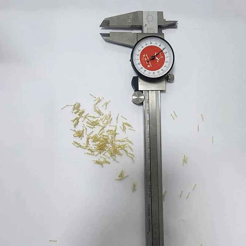
Available in tin-plated brass, gold-plated brass, phosphor bronze, and stainless steel. The product is manufactured through an integrated process combining precision turning and high-speed stamping. Dimensional tolerances are controlled within ±0.02mm, ensuring high component consistency suitable for automated, high-volume assembly.
Standard heights—0.8mm, 1.0mm, 1.2mm, 1.5mm, 2.0mm, 2.5mm, and 3.0mm—are kept in stock. For PCBs with unique structural requirements, non-standard height grounding pins can be developed to meet specific customer needs.
The unique flat base design prevents shifting during the SMT pick-and-place process. Tested to withstand 260°C reflow soldering temperatures, the components remain stable without detaching, deforming, or suffering from "floating" (lift-off) issues.
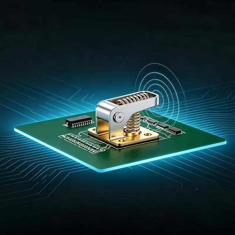
The SMT Ground Pin Brass Locating Standoff Hardware series encompasses three main categories: solid grounding posts, hollow grounding posts, and spring-loaded grounding pins (Pogo pins). The spring-loaded style compensates for tolerance variations caused by housing assembly deformation, maintaining stable electrical continuity even with slight structural shifts.
SMT grounding pins, SMT locating posts, PCB spacers/standoffs, spring-loaded Pogo grounding pins, bent grounding
terminals, fixed brass posts, and THT (Through-Hole Technology) brass posts.
Customers can select the ideal type based on assembly methods, structural space, and conductivity requirements;
combined orders for various structural configurations are also supported.
SMT Ground Pin Brass Locating Standoff Hardware are compatible with all PCBs utilizing shielding covers. They are widely used in consumer electronics, wireless communication modules, automotive ECUs, industrial control motherboards, and control boards for new energy equipment. Frequently paired with metal shielding housings, they are essential hardware components for EMC rectification during the hardware R&D phase.
All standard SMT grounding pins and brass locating standoffs are supplied in tape-and-reel packaging, allowing for direct loading onto automated SMT production lines. Our factory maintains stable, continuous mass production capabilities and can fulfill long-term supply contracts, ensuring uninterrupted production for customer projects.
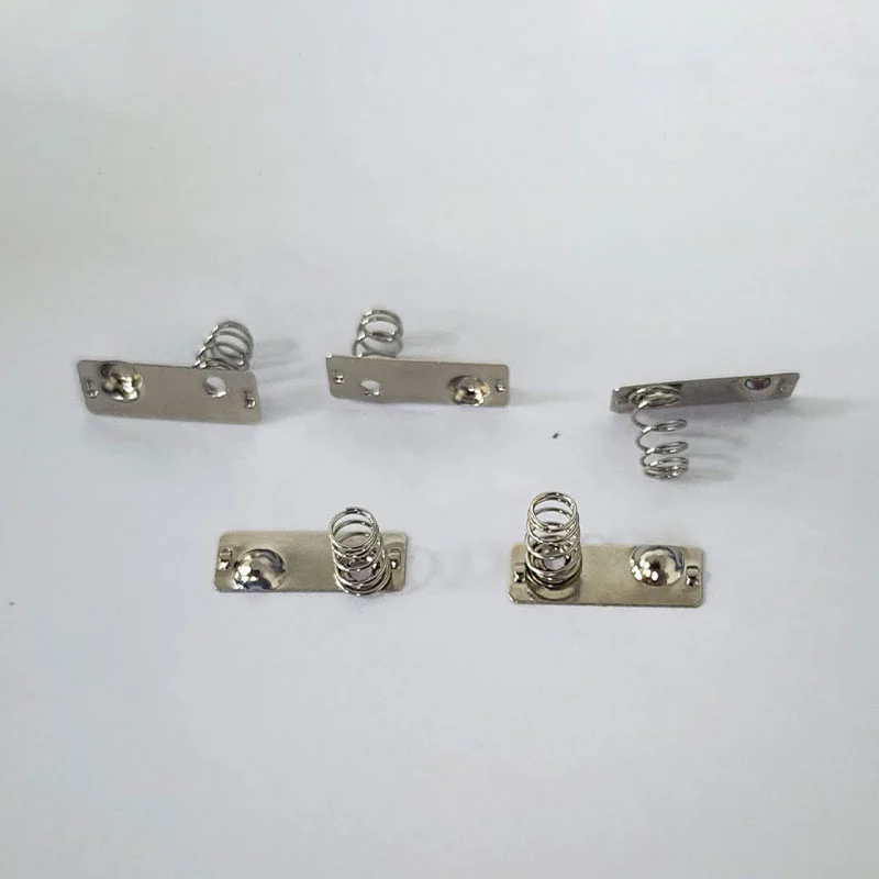
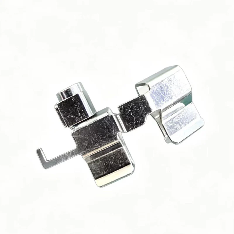
EMI conductive springs are elastic conductive components designed for electromagnetic shielding and low-impedance grounding applications; they are frequently paired with SMT grounding pins to form a complete grounding solution.
The main body is stamped from high-elasticity alloys such as C5191 phosphor bronze or beryllium copper. Surface plating options include gold, silver, and nickel to reduce contact resistance and enhance oxidation and corrosion resistance. They maintain stable conductivity over long-term use and exhibit minimal loss of elasticity after repeated compression, meeting the demands of up to one million contact cycles.
They withstand a wider temperature range and are less prone to aging or collapsing in high- or low-temperature environments. Their compact structure saves internal assembly space, and their superior resistance to permanent deformation makes them ideal for assembling small, high-density precision electronics.
They support various assembly methods—such as soldering, snap-in pre-installation, and pre-embedding within shielding frames—making them compatible with automated production lines and reducing manual assembly steps.
Once assembled, they form a continuous grounding path and fill gaps between the shielding cover, housing, and circuit board. This blocks electromagnetic leakage and external interference, helping the device pass EMI/EMC certifications faster and reducing the costs associated with repeated design revisions.
Parameters such as wire diameter, outer diameter, free height, and compression stroke can be adjusted based on customer drawings. Rapid delivery of small-batch prototypes supports testing, while mass production orders benefit from stable scheduling and strict quality control regarding dimensional accuracy and plating quality. Suitable for applications including RF modules, laptops, IoT terminals, automotive electronics, and various shielding cover grounding scenarios.
When standard off-the-shelf products do not meet structural requirements, engineers can rapidly assess mold-making feasibility based on drawings or samples to develop custom-specification grounding pins and conductive springs.
We accept small-batch trial orders during the early stages to facilitate prototype debugging and preliminary EMC testing; once the project design is finalized, we support stable, long-term, high-volume supply.
Based on PCB space constraints, operating frequency bands, and application environments, we assist customers in configuring complete grounding and shielding solutions—combining grounding pins, shielding cans, and EMI conductive springs.
A1: SMT grounding pins can be used in conjunction with bent shielding cans, drawn shielding cans, EMI conductive springs, and EMI grounding clips. As the direct manufacturer, we offer a one-stop solution for the entire grounding and shielding assembly, simplifying your supplier management.
A2: Single-point grounding often results in high grounding impedance and limited electromagnetic shielding effectiveness. Multi-point grounding pins enable equipotentiality within the shielding cavity, effectively reducing impedance and more than doubling shielding performance; this makes passing EMC tests easier and is a common solution for export-oriented electronic products.
A3: Our standard flat-base models are compatible with 260°C reflow soldering processes. They feature a stable structure that prevents shifting, detachment, or deformation (such as lifting) during standard SMT assembly, significantly reducing production defect rates.
A4: We offer four material options: tin-plated brass, gold-plated brass, phosphor bronze, and stainless steel. Gold-plated pins are suitable for high-frequency communication products; tin-plated pins are ideal for standard consumer electronics; and stainless steel pins are best for assemblies requiring high structural strength.
A5: We maintain stock in the following standard heights: 0.8mm, 1.0mm, 1.2mm, 1.5mm, 2.0mm, 2.5mm, and 3.0mm. Custom development based on drawings is available for specific height or structural requirements.
A6: Solid pins offer high rigidity and excellent positioning accuracy; hollow pins are lighter and reduce material costs; spring-loaded (Pogo) grounding pins provide elastic cushioning, compensating for assembly tolerances and ensuring continuous, stable electrical contact.
Address
Fumin Science and Technology Park, Songgang Subdistrict, Bao'an District, Shenzhen City, Guangdong Province, China
Tel