News

News

How Can SMT Ground Pin Brass Locating Standoff Hardware Improve PCB Grounding and Assembly Precision

2026-10-27 0 Leave me a message

Article Summary: Reliable grounding, accurate positioning, and stable mechanical connections are essential for modern electronic assemblies. SMT Ground Pin Brass Locating Standoff Hardware combines surface-mount installation with the functional advantages of brass hardware, helping manufacturers address PCB alignment, grounding continuity, and assembly consistency. This article explores its working principles, material benefits, design considerations, applications, quality requirements, and selection criteria to help engineers and purchasing teams identify a suitable solution for their electronic products.

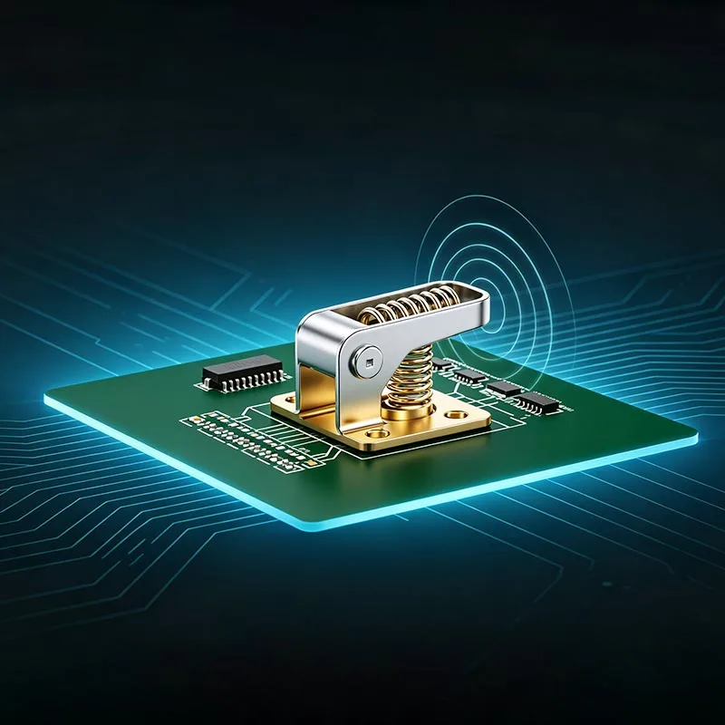
SMT Ground Pin Brass Locating Standoff Hardware

Table of Contents


What Is SMT Ground Pin Brass Locating Standoff Hardware?

Qiyiguo provides electronic interconnection solutions for applications where dependable electrical contact and accurate mechanical positioning are important. SMT Ground Pin Brass Locating Standoff Hardware is a specialized type of electronic mounting component designed to support positioning, grounding, or spacing functions in printed circuit board (PCB) assemblies, depending on its specific construction.

SMT stands for Surface Mount Technology, a manufacturing method that allows compatible electronic components and hardware to be mounted directly onto designated PCB pads. A locating feature helps guide components or mating structures into the intended position, while a grounding feature can establish an electrical path between conductive elements when the design provides the necessary contact.

The standoff function is equally important. By creating a defined separation between components or structural surfaces, a standoff can help maintain assembly geometry and reduce unwanted mechanical interference.

The principal functions of this type of hardware may include:

  • Grounding support: Establishing a conductive connection between designated components and a grounding network.
  • Mechanical positioning: Helping mating parts align correctly during assembly.
  • Spacing control: Maintaining a planned gap between boards, shields, panels, or other structures.
  • Assembly integration: Supporting automated placement and repeatable production when the component is designed for SMT processing.

Exact dimensions, mounting geometry, surface finish, and electrical ratings should be confirmed against the manufacturer's product drawing and technical specifications. These details determine whether a particular component matches the intended application.


How Does the Hardware Work in PCB Assemblies?

SMT Ground Pin Brass Locating Standoff Hardware integrates into an electronic assembly through a combination of surface mounting and mechanical engagement. Its actual operating principle depends on the contact geometry, PCB layout, and intended grounding arrangement.

1. Surface Mounting

During a typical SMT process, solder paste is applied to the designated PCB pads. The hardware is positioned according to the assembly design and passes through a compatible reflow process. The solder joints provide mechanical attachment and, where the pad design is electrically connected to ground, may contribute to the grounding path.

2. Positioning and Alignment

The locating feature helps guide a mating component into the correct position. This can be valuable in compact assemblies where small alignment errors affect connector engagement, shield placement, or enclosure fit.

3. Electrical Grounding

When the component is designed to conduct electricity, its conductive body and associated contact interfaces can provide a grounding path. The complete path may include the hardware, solder joint, PCB ground pad, and connected ground plane or chassis interface.

Designers should verify contact resistance, current capacity, and grounding continuity under the intended operating conditions. A brass body alone does not guarantee effective grounding; the entire electrical path must be designed and validated.


Why Is Brass a Suitable Material?

Brass is a copper-based alloy widely used in precision hardware because it offers a useful combination of electrical conductivity, machinability, and mechanical workability. Its suitability depends on the alloy grade, component geometry, operating environment, and required electrical performance.

For SMT grounding and locating applications, brass can offer several practical benefits:

  • Electrical conductivity: Brass can support conductive connections when the alloy, dimensions, and contact interfaces meet the application's requirements.
  • Manufacturing flexibility: Many brass grades are suitable for precision machining, forming, and the production of small hardware components.
  • Dimensional consistency: Appropriate manufacturing controls can help maintain the locating dimensions needed for repeatable assembly.
  • Surface finish options: Compatible plating or finishing treatments may improve solderability, corrosion resistance, or contact performance.
  • Application versatility: Brass components can be engineered for a range of electronic products and mounting arrangements.

Material selection should not rely on the word "brass" alone. Engineers should review the specified alloy grade, hardness, conductivity, and finish. Where soldering is required, the surface treatment must also be compatible with the solder alloy and reflow profile.


What Advantages Does This Hardware Offer?

When correctly specified and integrated, SMT Ground Pin Brass Locating Standoff Hardware can help manufacturers improve several aspects of PCB assembly and product design.

More Consistent Assembly Positioning

Locating features help establish repeatable component placement and mating geometry. This can reduce alignment-related assembly difficulties and simplify the integration of shields, brackets, and other electronic hardware.

Potentially More Efficient Production

SMT-compatible hardware can be incorporated into an established surface-mount workflow when its package, thermal characteristics, and construction support automated handling and reflow soldering. Suitable designs may reduce the need for separate manual installation operations.

Integrated Mechanical and Electrical Functions

A component designed to perform both locating and grounding functions can reduce the need for separate parts in certain applications. However, integration is beneficial only when the combined component satisfies the mechanical and electrical requirements simultaneously.

Compact Design Support

Electronic products continue to require efficient use of PCB space. Small-format mounting hardware can help designers manage spacing, alignment, and grounding within constrained layouts, provided adequate pad dimensions, electrical clearances, and assembly access are maintained.

These advantages depend on the selected design, PCB layout, production process, and verification results rather than on the component category alone.


Where Is SMT Ground Pin Hardware Used?

SMT grounding and locating hardware can serve a variety of electronic assembly requirements. Potential applications include:

  • Consumer electronics: Supporting compact PCB assemblies, internal brackets, and conductive shielding structures.
  • Communication equipment: Helping maintain defined mechanical interfaces and grounding connections in communication modules.
  • Industrial electronics: Supporting repeatable board positioning and grounding arrangements in control equipment.
  • Automotive electronics: Serving as a potential hardware option for electronic modules when the component and assembly meet applicable automotive requirements.
  • Electronic shielding systems: Helping establish mechanical contact or grounding interfaces for compatible shielding components.
  • Modular PCB assemblies: Maintaining specified spacing and alignment between related structural elements.

Application suitability must be assessed individually. Automotive, industrial, and high-frequency designs may require additional validation for vibration, temperature cycling, corrosion, grounding impedance, or electromagnetic compatibility.


How Should Engineers Select the Right Standoff?

Selecting appropriate SMT Ground Pin Brass Locating Standoff Hardware begins with a clear understanding of the assembly's mechanical and electrical requirements. A component that fits physically may still be unsuitable if its solder joints, grounding path, or locating tolerances do not meet the design specification.

Selection Factor What to Check Why It Matters
Dimensions Overall height, diameter, locating-pin size, and mounting footprint Ensures physical fit and correct alignment.
Material Brass alloy grade and mechanical properties Influences conductivity, machinability, and durability.
Surface Finish Tin, nickel, or other specified compatible finishes Affects solderability, corrosion behavior, and contact performance.
Electrical Requirements Contact resistance, current, and grounding continuity Helps establish a dependable electrical path.
Mounting Design PCB pad geometry, solder-paste requirements, and retention Supports reliable assembly and mechanical attachment.
Environmental Conditions Temperature, humidity, vibration, and exposure to contaminants Helps determine long-term application suitability.
Production Compatibility Placement method, reflow profile, and packaging format Supports consistent manufacturing performance.

Before placing a production order, engineering teams should obtain the relevant technical drawing, confirm tolerances, and evaluate samples in the intended PCB assembly. If a standard configuration does not satisfy the design, discuss possible dimensional, material, or finish adjustments with the supplier.


Which Manufacturing and Quality Factors Matter?

Reliable electronic hardware requires more than suitable raw material. Manufacturing consistency, dimensional control, surface quality, and verification procedures all influence the final component's performance.

Precision and Dimensional Inspection

Locating features must remain within the tolerances specified by the product design. Measurements should cover the critical dimensions that affect PCB placement, mating-part alignment, and component clearance.

Material and Finish Verification

Material documentation and surface-finish controls help ensure that production components match the approved specification. Finish thickness, coverage, adhesion, and solderability should be assessed where relevant to the application.

Electrical Performance Testing

For grounding hardware, electrical testing can verify continuity and evaluate contact resistance against established acceptance criteria. Testing should reflect the actual connection path rather than measuring the metal body alone.

Process Compatibility

SMT hardware must be compatible with the intended solder paste, reflow profile, placement method, and PCB pad design. Trial assembly can reveal issues such as poor wetting, component movement, or inadequate solder-joint formation before volume production begins.

Manufacturers and buyers should agree on inspection methods, acceptance criteria, documentation, and traceability requirements before mass production. Any claims concerning certifications or compliance should be confirmed through current, applicable documentation.


How Does It Compare with Other PCB Hardware?

Different hardware types address different mounting requirements. The following comparison highlights the general differences between SMT grounding and locating hardware and other common PCB mounting options.

Hardware Type Primary Function Typical Mounting Approach Main Consideration
SMT Ground Pin Brass Locating Standoff Locating, spacing, and potentially grounding Surface mounting on compatible PCB pads Requires compatible geometry and validated electrical connections.
Conventional PCB Standoff Board spacing and mechanical support Typically screw-mounted or otherwise mechanically fastened May require additional assembly steps and mounting clearance.
SMT Grounding Clip Grounding or contact with a shield or enclosure Surface mounting on a designed PCB footprint Contact force and mating-surface geometry are important.
Through-Hole Ground Pin Electrical connection and mechanical retention Inserted into plated or unplated PCB holes as designed Requires suitable hole geometry and a compatible soldering process.
Nonconductive Spacer Mechanical separation and insulation Mounted using a design-specific fastening method Does not provide an electrical grounding path.

The best choice depends on the intended function. If both positioning and grounding are required, engineers should compare integrated hardware with separate locating and grounding components to determine which arrangement provides the best balance of space, assembly efficiency, and reliability.


What Are the Best Installation Practices?

Correct installation is essential for achieving the expected performance of SMT hardware. Even a precisely manufactured component can underperform when the PCB footprint, soldering process, or mating structure is unsuitable.

Use the following checklist during design validation and production setup:

  1. Review the product drawing: Confirm dimensions, tolerances, mounting orientation, and the intended grounding interface.
  2. Verify the PCB footprint: Check pad size, copper design, solder-mask clearance, and ground-plane connectivity.
  3. Confirm soldering compatibility: Validate solder paste, placement settings, and reflow conditions for the actual component.
  4. Inspect solder joints: Check for incomplete wetting, insufficient solder, bridging, movement, or other process defects.
  5. Test electrical continuity: Measure the complete grounding path against the project's acceptance criteria.
  6. Validate mechanical fit: Confirm that mating parts align correctly without applying excessive force to the hardware or PCB.
  7. Perform application-specific testing: Evaluate vibration, temperature, corrosion, or repeated assembly where the product's operating environment requires it.

For ongoing production, retain approved drawings and inspection records, monitor process variation, and investigate any changes in grounding performance or assembly yield. These practices help identify potential issues before they affect finished products.


Frequently Asked Questions

1. What is SMT Ground Pin Brass Locating Standoff Hardware used for?

It is designed for surface-mount electronic assemblies that require one or more functions such as component positioning, mechanical spacing, or electrical grounding. The exact capabilities depend on the component's geometry and electrical design.

2. Why is brass commonly considered for grounding hardware?

Brass offers useful electrical conductivity and machinability, making it suitable for many precision electronic hardware applications. The specific alloy and surface finish should be selected according to conductivity, mechanical strength, solderability, and environmental requirements.

3. Can this hardware be installed using an automated SMT production line?

It can be used in automated SMT production when the particular design supports machine placement, suitable packaging, and the intended reflow-soldering process. Confirm the manufacturer's handling and processing recommendations before production.

4. Does a brass locating standoff automatically guarantee reliable grounding?

No. Reliable grounding depends on the complete conductive path, including the hardware, solder joint, PCB ground connection, and any mating interface. Electrical continuity and contact resistance should be validated in the assembled product.

5. Which surface finish should buyers choose?

The appropriate finish depends on the application, soldering process, corrosion exposure, and electrical contact requirements. Tin and nickel are examples of finishes used for electronic hardware, but the final choice should be confirmed against the component specification and assembly conditions.

6. What information should be provided when requesting a quotation?

Provide the product drawing, dimensions, required brass grade, finish, tolerances, electrical requirements, expected order quantity, and intended application. PCB footprint details and environmental requirements are also useful for assessing compatibility.

7. How can buyers verify product quality before mass production?

Request technical drawings, material and finish specifications, inspection criteria, and representative samples. Evaluate dimensional accuracy, solder-joint quality, electrical continuity, and mechanical fit under the intended application conditions before approving volume production.


Conclusion

SMT Ground Pin Brass Locating Standoff Hardware can provide a practical solution for electronic assemblies that require accurate positioning, controlled spacing, and a dependable grounding interface. By evaluating material properties, dimensional tolerances, surface finish, solderability, and electrical performance together, engineers can make more informed hardware decisions and reduce avoidable assembly problems. Choosing a suitable supplier is equally important for maintaining consistent specifications and reliable production results. If you are sourcing precision electronic hardware or evaluating a customized locating and grounding solution, explore the relevant product details on Qiyiguo's SMT Ground Pin Brass Locating Standoff Hardware product page, prepare your technical requirements, and contact us to discuss your application, request product information, and identify a solution aligned with your PCB design and manufacturing needs.

Related News
Leave me a message
X
We use cookies to offer you a better browsing experience, analyze site traffic and personalize content. By using this site, you agree to our use of cookies. Privacy Policy
RejectAccept