E-mail
WhatsApp



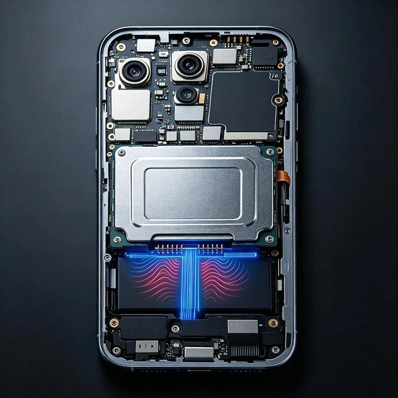
As electronic products become increasingly thin and compact, the space available for electrical connections whether between PCBs, between a PCB and a battery, or between a PCB and an antenna module is extremely limited.
Traditional solutions often fall short: FPC (Flexible Printed Circuits) consume significant surface area and have limited bending durability; board-to-board connectors are often too tall and costly; and direct soldering prevents disassembly and offers no tolerance compensation.
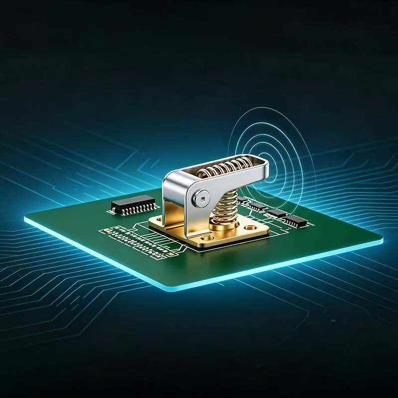
Double Ended Pogo Pin Connectors simultaneously address three key challenges: electrical connection, tolerance compensation, and detachable assembly. Featuring retractable spring-loaded pins at both ends, they are sandwiched between two PCBs, utilizing bidirectional spring force to maintain stable, elastic contact with the contact points on both sides. Furthermore, their overall height can be kept extremely low, freeing up valuable space for structural design.


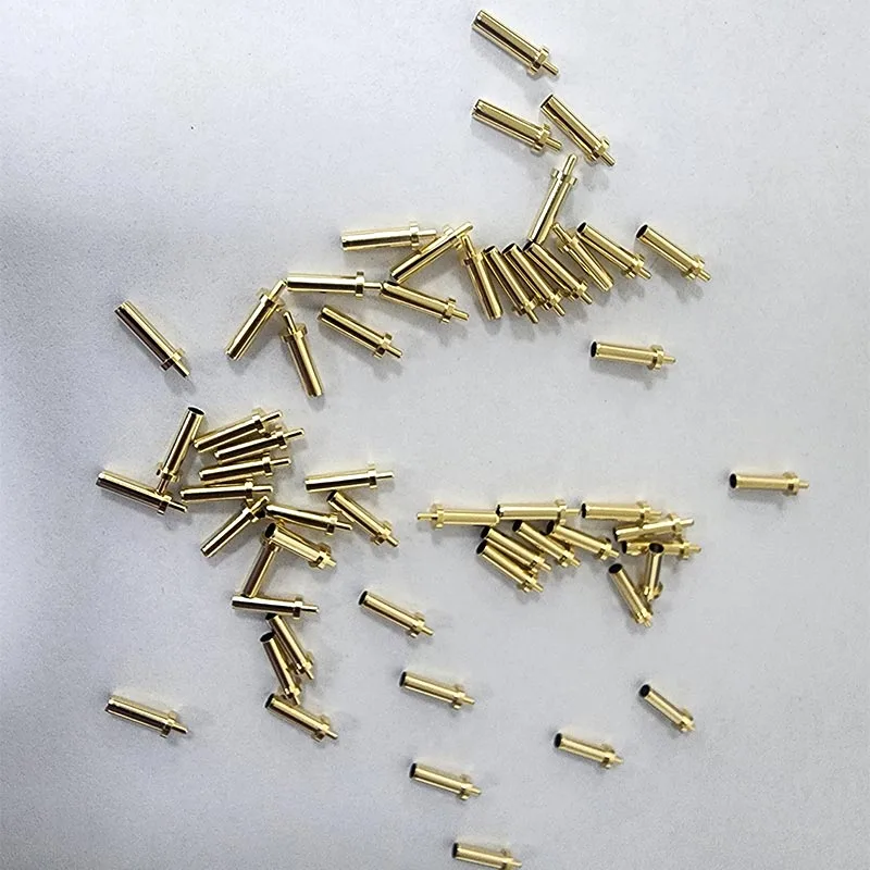
The core structure of a Double Ended Pogo Pin Connector consists of five components:
Top Plunger: Makes contact with the upper PCB pad or contact point; the tip shape is customizable (e.g., pointed, rounded, or claw-shaped) and features a gold-plated surface.
Top Spring: Provides continuous downward spring force to the top plunger, ensuring stable contact with the upper contact point.
Body/Tube: A hollow, conductive tube open at both ends; it serves as the primary channel for current conduction while housing all internal components.
Bottom Spring: Provides continuous upward spring force to the bottom plunger, ensuring stable contact with the lower contact point.
Bottom Plunger: Makes contact with the lower PCB pad or contact point; its structure mirrors that of the top plunger.
The double-ended pogo pin is sandwiched between two PCBs (or between a PCB and components such as a battery or antenna), with the plungers at the top and bottom ends pressing against the contact pads on either side.
The internal dual-spring structure continuously applies elastic preload to the contact pins at both ends; even if spacing variations arise due to assembly tolerances, vibrational displacement, or thermal expansion and contraction the pins automatically extend or retract to compensate, ensuring consistent contact pressure.
The current path flows from the upper PCB pad through the top pin, the barrel, and the bottom pin to the lower PCB pad, establishing a complete, low-impedance conductive pathway.
| Comparison Dimension | Traditional FPC Flexible Cable | Single-ended Spring Pin with SMT Pad | Double-ended Spring Pin |
| Connection Method | Soldering or snap-in fastening | One end soldered / SMT mounted, the other end for elastic contact | Elastic contact on both ends |
| Tolerance Compensation | None | Unidirectional compensation | Bidirectional compensation |
| Removability | Poor | Removable on one side | Removable on both sides |
| Space Occupation | Relatively large | Medium | Extremely compact, profile height as low as 2–3 mm |
| Vibration Resistance | Average | Good | Excellent (bidirectional elastic preload) |
| Application Scenarios | Large-area board-to-board connection | Fixed board plus movable module | Dual movable boards / dual-PCB stacking assembly |
The core advantage of Double Ended Pogo Pin Connectors lies in scenarios where neither connection point is a fixed reference surface (such as with two PCBs that require independent removal/installation or undergo relative movement): only dual-ended spring pins can provide elastic compensation and reliable contact in both directions simultaneously.
● Dual-Action: Both ends move independently; suitable for scenarios involving tolerances or displacement on both sides, offering maximum compensation capability.
● Single-Action: One end is fixed while the other moves; suitable for scenarios where one side is a fixed reference surface and the other requires elastic compensation; features a more compact structure.
● Signal-type double-ended pogo pins: Used for high-frequency signal transmission; emphasizes low contact resistance and high-frequency performance; suitable for semiconductor testing, communication modules, etc.
● High-current double-ended pogo pins: Used for power transmission; emphasizes low impedance and high current-carrying capacity; suitable for battery connections, charging modules, etc.
● Floating double-ended pogo pins: Features an internal floating compensation structure supporting automatic alignment for lateral deviations of ±0.3mm; suitable for assembly scenarios with limited alignment precision.
● Semiconductor test fixtures: Chip packaging tests and wafer-level tests the high precision and low contact resistance (≤30mΩ) of double-ended pogo pins ensure signal accuracy and support high-frequency testing (5–40GHz).
● Wearable devices: Connections between internal batteries and mainboards in smartwatches/smart bands their ultra-compact size and bidirectional elastic compensation perfectly suit the tight internal spaces of wearable devices.
● TWS earbud charging cases: Charging contacts between earbuds and the case the double-ended structure naturally meets the dual-sided contact requirements of the "charging case base + earbud contact" interface.
● E-cigarettes: Connections between the atomizer coil and the battery unit high-current double-ended pogo pins. The pin supports currents ranging from 3A to 10A, meeting the power requirements for atomization heating.
● 5G Communication Modules: Signal connection between the RF module and the mainboard high-frequency dual-ended pogo pins meet the high-bandwidth signal transmission requirements of 5G millimeter-wave frequency bands.
● Medical Equipment: Modular connections for portable medical devices detachable features facilitate equipment maintenance, disinfection, and cleaning.
● Automotive Electronics: BMS (Battery Management Systems) and in-vehicle sensor modules the vibration resistance of dual-ended pogo pins meets the rigorous demands of the automotive environment.
| Component | Common Materials | Process Features |
| Pin Tip | Beryllium Copper (BeCu), SK4 Tool Steel | Precision turning with gold-plated surface to ensure low contact resistance and wear resistance |
| Barrel | Phosphor Bronze Alloy, Brass C3604 | Deep-drawing forming with precision-machined inner wall to guarantee electrical conductivity and structural strength |
| Spring | Piano Wire (SWP), Stainless Steel Wire (SUS) | Special heat treatment to maintain long-term stable elasticity |
| Sliding Component (Dual-action Type) | Conductive Copper Alloy | Precision machining with dual-cavity separation to enable independent bidirectional movement |
● Gold-over-Nickel Plating: The most common solution; the nickel underlayer enhances corrosion resistance, while the gold layer ensures ultra-low contact resistance and oxidation resistance.
● Nickel + Silver Plating: Suitable for high-current applications; the silver layer offers higher electrical conductivity.
● Nickel + Tin Plating: A cost-optimized solution suitable for applications with less stringent contact resistance requirements.
● Precision CNC Turning: Pin heads and barrels are machined using high-precision CNC lathes, achieving diameter tolerances as tight as ±0.01mm.
● Deep-Draw Forming: Pin barrels are manufactured using a deep-drawing process, ensuring uniform wall thickness and consistent internal diameters.
● Dual-Cavity Precision Assembly: Double Ended Pogo Pin Connectors utilize a sliding component to precisely divide the barrel's interior into two independent cavities, ensuring bidirectional movement without interference.
● Precision Crimping: Pin heads, springs, and sliding components are assembled via precision crimping to ensure assembly consistency and structural integrity.
● Vacuum Plating: Ensures uniform coating coverage on both the interior of the barrel and the contact surfaces.
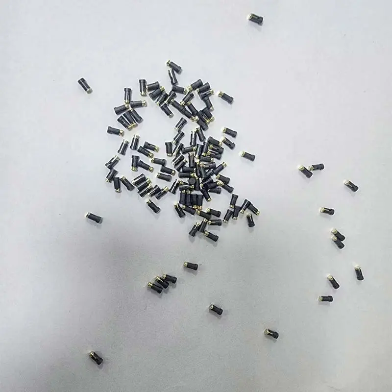
● Outer Diameter Range: 0.3mm - 6.0mm (customization for smaller sizes available)
● Total length range: 2.0mm – 30.0mm
● Travel range: 0.5mm – 5.0mm (single-end travel)
● Contact resistance: ≤30mΩ (dynamic); ≤10mΩ achievable with gold plating
● Rated current: 0.5A – 3A (standard models); high-current models available up to 5A – 100A+
● Mechanical life: ≥100,000 compression cycles
● Operating temperature range: -40°C to +120°C (extended ranges available for specific models)
● Dimensional precision: Diameter ±0.02mm, height ±0.05mm
● Spring force range: 20g – 500g (customizable)
● Salt spray resistance: 24 hours to 1,000+ hours (depending on plating specifications)
● High-frequency performance: Supports 5 – 40GHz signal transmission (semiconductor test types)
● Floating compensation: Automatic alignment for ±0.3mm lateral deviation (floating models)
● Compliance: RoHS 2.0 and REACH compliant
We hold both ISO 9001 and IATF 16949 certifications, possessing comprehensive quality management capabilities to serve global Tier 1 and OEM customers.
● Optical Projector & CMM (Coordinate Measuring Machine) – Dimensional accuracy inspection
● Contact Resistance Tester – Electrical performance testing
● Spring Force Tester – Bi-directional spring force and travel/stroke testing
● Hardness Tester – Material hardness testing
● Coating Thickness Tester (X-Ray) – Plating thickness testing
● Salt Spray Chamber – Corrosion resistance testing
● Life Cycle Tester – Bi-directional compression life verification
Custom development of double-ended pogo pin connectors with independent upper and lower cavities. The internal sliding component precisely separates the barrel into two independent chambers, enabling bidirectional movement without mechanical interference. Supports both dual-action (both ends move independently) and single-action (one end fixed, one end moves) configurations based on your assembly requirements.
Top and bottom plunger tips can be specified independently. Available tip types include B (pointed), J (rounded), J1 (small rounded), U (claw/crown), and U1 (small claw/crown). For example, pointed tip on top for piercing oxide layers + rounded tip on bottom for standard pad contact customized to match your specific mating surface conditions on each side.
Top and bottom spring forces are independently adjustable. Range: 20g–500g per end. This allows precise force matching to your contact pad requirements lighter force for delicate pads, heavier force for high-vibration environments. Our engineering team provides force simulation recommendations within 48 hours based on your assembly stack-up.
Custom development of floating double-ended pogo pins with internal automatic alignment capability. Supports lateral deviation compensation of ±0.3mm, ideal for assembly scenarios with limited alignment precision between two PCBs or modules.
Custom impedance matching for signal-type double-ended pogo pins supporting 5–40GHz high-frequency transmission. Design parameters including contact geometry, barrel inner diameter, and insulation materials are optimized for 50Ω characteristic impedance to minimize signal reflection and insertion loss in RF and semiconductor test applications.
Custom development for power transmission applications with current ratings from 5A to 100A+. Material selection (beryllium copper for high conductivity), cross-sectional area optimization, and plating type (silver plating recommended) are coordinated to achieve low temperature rise under continuous current load.
Overall length range: 2.0mm–30.0mm. Single-end travel range: 0.5mm–5.0mm. Custom height profiles are developed to match your PCB stack-up, connector housing constraints, and compression distance requirements.
Standard range 0.3mm–6.0mm. For ultra-compact devices such as TWS earbuds and smart wearables, we support custom development of sub-0.3mm diameter pins to meet extreme space constraints.
Each custom design undergoes comprehensive force testing on both ends using dedicated bi-directional spring force testers. Force-travel curves for both top and bottom springs are documented and provided with sample shipments for customer validation.
Double-ended pogo pins are supplied in tape-and-reel packaging with orientation and pitch customized to match your automated assembly line feeders. Supports high-speed pick-and-place for both top-side and bottom-side contact applications.
A1: Dual-action pins allow both plungers to move independently, providing bidirectional tolerance compensation ideal when both contact surfaces have position uncertainty. Single-action pins have one fixed end and one moving end, offering a more compact structure ideal when one side is a fixed reference surface and only the other side requires elastic compensation. Selection depends on your assembly stack-up and which side has positional tolerance.
A2: Yes. Top and bottom tip types can be specified independently. Available options include B (pointed), J (rounded), J1 (small rounded), U (claw/crown), and U1 (small claw/crown). For example, a pointed tip on top can pierce oxide layers on uneven surfaces, while a rounded tip on bottom provides standard pad contact. We offer free tip configuration recommendations based on your mating surface conditions.
A3: Standard signal-type models support 0.5A–3A. High-current models are available from 5A up to 100A+, depending on pin diameter, material selection (beryllium copper recommended for high conductivity), and plating type (silver plating recommended for high-current applications). We provide specific ampacity recommendations based on your power requirements and operating temperature.
A4: Floating double-ended pogo pins incorporate an internal floating compensation structure that allows automatic alignment for lateral deviations up to ±0.3mm. This is particularly useful in assembly scenarios where two PCBs or modules have limited alignment precision, such as modular device connections or hot-swappable assemblies. The floating mechanism ensures consistent electrical contact even with slight positional offsets.
A5: For signal-type double-ended pogo pins optimized for high-frequency performance, we support bandwidths from 5GHz up to 40GHz. Design parameters — including contact geometry, barrel inner diameter, and insulation materials — are optimized for 50Ω characteristic impedance to minimize signal reflection and insertion loss, making them suitable for semiconductor testing and RF module applications.
A6: With an outer diameter range of 0.3mm–6.0mm and total length customizable from 2.0mm upwards, we can achieve ultra-low profile heights to meet the strict space constraints of wearable devices, TWS earbuds, and other compact electronics. Single-end travel is typically 0.5mm–5.0mm, selected based on your assembly tolerance stack-up requirements.
Address
Fumin Science and Technology Park, Songgang Subdistrict, Bao'an District, Shenzhen City, Guangdong Province, China
Tel